
Creating a Test Plan - CE 302502
The CE 302502 option is used for EU CE (RED) certification testing of 5.8 GHz Broadband Fixed Wireless Access (BFWA) data transmitting systems per EN 302 502.
Basic Settings
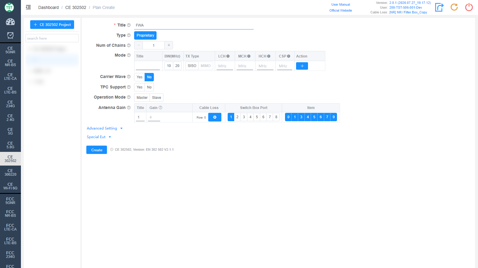
Title: Test plan name, entered by the user.
Type: Technical category, Proprietary (custom configuration).
Num of Chains: Number of transmit chains (antennas) the product has.
Mode: Custom mode table:
Title: Mode number; other names can be manually input according to customer requirements.
BW(MHz): Channel bandwidth, selectable 10 / 20 MHz.
TX Type: Transmission type, SISO / MIMO.
LCH / MCH / HCH: Low / middle / high channel frequency settings (MHz).
CSP: Channel Spacing.
Action: Used to add / delete mode configuration rows.
Carrier Wave: Whether the product supports carrier wave transmission. If Yes is selected, the frequency error will be measured in carrier wave mode.
TPC Support: Confirm whether the product supports TPC (Transmit Power Control). Affects the power-related limits.
Operation Mode: Operating mode of the product: Master (master device, which actively performs channel checks) / Slave (slave device).
Antenna Gain:
Title: Antenna number, named sequentially by default as 1, 2, 3, 4....
Gain: Gain of each antenna.
Cable Loss: Cable loss of the RF cable from the product's antenna port to the Switch Box or the SA (spectrum analyzer). How to Create Common Cable Loss.
Switch Box Port: Port number of the switch connected to the product's antenna.
Item: Test items for each antenna; the numbers correspond as follows:
(C30250200) Duty Cycle
(C30250201) Frequency Error
(C30250203) Transmitter RF Output Power
(C30250204) EIRP Spectral Power Density
(C30250205) Transmitter Unwanted Emissions Outside The 5 725 MHz To 5 875 MHz Band
(C30250206) Transmitter Unwanted Emissions Within The 5 725 MHz To 5 875 MHz Band
(C30250207) Receiver Spurious Emissions
(C30250209) Receiver Blocking
The software preselects the default test items according to the technical characteristics. Note: In some cases, test parameters are mutually referenced between items; it is recommended to create the test plan with the default items.
Advanced Setting and Special Eut Settings
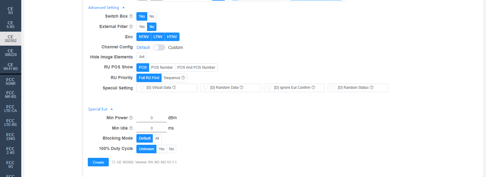
The following settings can generally be kept at their default values. Adjust them only when the test results are abnormal or there are special test requirements.
Switch Box: Whether to use a Switch Box. If a Switch Box has not been purchased, select No, and the product will be directly connected to the spectrum analyzer for testing.
External Filter: Whether an external filter is used in the RF path during testing.
Env: Environmental conditions to test, multi-select: NTNV / LTNV / HTNV (normal temp normal volt / low temp normal volt / high temp normal volt).
Channel Config: Channel configuration, Default or Custom (manually customized channels).
Hide Image Elements: Select the elements to hide in report images (e.g., the Ant antenna marker).
RU POS Show: How the RU position is displayed in the report: POS / POS Number / POS And POS Number.
RU Priority: RU test priority: Full RU First / Sequence.
Special Setting: Special settings. Options prefixed with [D] are debug options and do not need to be checked for normal testing:
[D] Virtual Data / [D] Random Data / [D] Ignore Eut Confirm / [D] Random Status: Debug options.
Min Power: Sets the minimum power (dBm); 0 means automatic.
Min Idle: Minimum idle time (ms).
Blocking Mode: Receiver blocking test mode: Default / All.
100% Duty Cycle: Whether the sample's duty cycle is 100% (Unknown / Yes / No); only needs to be selected when the system misjudges the duty cycle.
Referenced regulations (displayed next to the Create button): CE 302502, Version: EN 302 502 V2.1.1